Equipment Requirements
In order to produce a quality socket fusion, the following equipment is required for this procedure
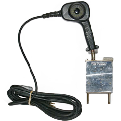
- Apparatus - Socket fusion tools manufactured in accordance with ASTM F1056
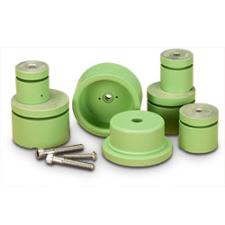
- Heating Tool Faces - Consisting of two parts, a male end for the interior socket surface and a female end for the exterior pipe surface.
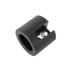
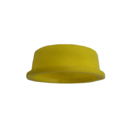
- Rounding Clamps (Cold Ring) - Device to maintain the roundness of the pipe and control the depth of pipe insertion into the socket during the joining operation.
- Depth Gauge - Proper positioning of the rounding clamp.
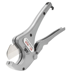
- Chamfering Tool - Device to bevel the end of the pipe. The depth gauge and chamfering tool may be combined into a single tool.
- Holding Tools - Recommended for socket fusion of 2”IPS and larger pipe and fittings.
Heater Temperature
Heater Surface Temperature: Minimum 490°F - Maximum 510°F (254 - 266°C )
In order to obtain a proper melt, a uniform temperature must be maintained across the heating surface. All points on both heating surfaces where the heating surfaces will contact the pipe and fitting must be within the prescribed minimum and maximum temperatures. Heating tool surfaces must be clean.
Procedure
1. Preparation
1. Verify heating temperature is within the specified temperature range (490°F - 510°F ).
2. Cut the pipe end squarely, and clean the pipe end and fitting, both inside and out with a clean, dry, lint-free cloth. Do not touch cleaned surfaces with your hands.
3. Chamfer the outside edge of the pipe end slightly. The pipe should be free of debris and burrs.
4. Place the cold ring on the pipe as determined by the depth gauge - Place the depth gauge over the chamfered end of the pipe. Clamp the cold ring immediately behind the depth gauge.
2. Heating
1. Review the recommended heating times in Table VI. The heating time begins after Step C has been completed.
2. Insert the fitting onto the male heating face. The fitting should be held against the back surface of the male heater face.
3. Insert the pipe into the female heating face. The female socket heating face should be against the cold ring clamp.
4. Hold the pipe and fitting in place against the heater faces for the recommended heating time as shown in Table VI.
3. Fusion and Cooling
1. At the end of the heating time, simultaneously remove the pipe and fitting straight out from the tool using a “snap” action. Do not torque or twist the pipe or fitting during removal.
2. A QUICK inspection should be made of the melt pattern on the pipe end and fitting socket. If there is evidence of an incomplete melt pattern, do not continue with the fusion procedure.
3. Immediately insert the pipe straight into the socket of the fitting so that the cold ring is flush against the end of the fitting socket. While cooling, pressure should be maintained on the fusion per the recommended cooling time shown in Table VI.
4. Allow the joint to cool an additional five (5) minutes before removing the cold ring. An additional 10 minutes of cooling time is recommended before exposing the joint to any type of stresses (ie., burial or testing).
4. Inspection
Visually inspect the weld. A complete impression of the rounding clamp should be visible in the melt pattern at the end of the socket. There should be no gaps, voids or unbonded areas.
Qualification
1. Prepare a sample joint such as a coupling with pipe socket fused to both ends. The pipe should be at least 6” or 15 times the wall thickness in length.
2. Observe the fusion process and verify the recommended procedure for socket fusion is being followed.
3. Visually inspect the sample joints for quality.
4. Allow the sample to cool completely (minimum of one hour).
5. 5. Prepare test straps as shown in Figure III. Cut the joints lengthwise into at least three longitudinal straps with a minimum of 1Ó or 1.5 times the wall thickness in width.
6. Visually inspect the cut joint for any indications of voids, gaps, misalignment or surfaces that have not been fused.
7. Bend each test strap 180° with the inside of the pipe facing out.
8. The fusion joint must be free of cracks, voids, gaps and separations. If failure does occur at the weld in any of the samples, then the fusion procedure should be reviewed and corrected. After correction, another sample weld should be made per the new procedure and re-tested.
